Skip to content
Home » 3D Printing » Page 2

3D Printing

3D Printing Information, How-To’s, Tips, Tools, and Guides

UPDATE NEW RASPBERRY PI 4 FIRMWARE / EEPROM

This guide assumes you do not have a running Raspberry Pi 4 device, and this is your first time opening it up. If that is the case, make sure you follow the steps in this guide first
https://tacticalware.com/install-raspbian-os-on-raspberry-pi-4/

Once your Operating system is setup and functional you will want to update the firmware to the latest revision, therefore the objective of this guide is to show you how to update Raspian and how to update the eeprom / firmware

Open a terminal
sudo bash
apt update
apt upgrade
rpi-update

Would you like to proceed
Type y
Now reboot your Pi

Open a terminal
sudo bash
rpi-eeprom-update -d -a
reboot your Pi after it updates

Open a terminal
raspi-config
Scroll down and select Option 8 – Update
Update now runs, and after the update completes
Scroll down and select Option 6 – Advanced Options
Then scroll down to Option A7 – Bootloader Options
Select Option E1 Latest – Use the latest version of the boot rom software
Press Enter
Select OK
On the Reset boot rom to defaults screen
Select No
On the Boot rom not reset to defaults screen
Select OK
Scroll down and select Finish
Select Yes

Your Firmware / EEPROM are now Updated, and you will have the latest version with the latest features.

Hardware I used:
Raspberry Pi 4 (4gb)
https://amzn.to/3q551IO

SanDisk 32GB Ultra microSDHC UHS-I Memory Card with Adapter
https://amzn.to/2Vfvo0y

CanaKit 3.5A Raspberry Pi 4 Power Supply (USB-C)
https://amzn.to/3fNTYPu

CanaKit Raspberry Pi 4 Micro HDMI Cable – 6 Feet
https://amzn.to/33u5hr9

Thanks for reading!
UDATE EXISTING RASPBERRY PI 4 FIRMWARE / EEPROM

This guide assumes you already have a running Raspberry Pi 4 device. If you do not already have it setup, you can follow this guide first (https://tacticalware.com/install-raspbian-os-on-raspberry-pi-4/)

This objective of this guide is to show you how to update Raspian and how to update the eeprom / firmware

Open a terminal
sudo bash
apt update
apt upgrade
rpi-update

Would you like to proceed
Type y
Now reboot your Pi

Open a terminal
sudo bash
rpi-eeprom-update -d -a
reboot your Pi after it updates

Open a terminal
raspi-config
Scroll down and select Option 8 – Update
Update now runs, and after the update completes
Scroll down and select Option 6 – Advanced Options
Then scroll down to Option A7 – Bootloader Options
Select Option E1 Latest – Use the latest version of the boot rom software
Press Enter
Select OK
On the Reset boot rom to defaults screen
Select No
On the Boot rom not reset to defaults screen
Select OK
Scroll down and select Finish
Select Yes

Your Firmware / EEPROM are updated, and you will have the latest version with the latest features.

Hardware I used:
Raspberry Pi 4 (4gb)
https://amzn.to/3q551IO

SanDisk 32GB Ultra microSDHC UHS-I Memory Card with Adapter
https://amzn.to/2Vfvo0y

CanaKit 3.5A Raspberry Pi 4 Power Supply (USB-C)
https://amzn.to/3fNTYPu

CanaKit Raspberry Pi 4 Micro HDMI Cable – 6 Feet
https://amzn.to/33u5hr9


Thanks for Reading!

INSTALL RASPBIAN OS ON RASPBERRY PI 4

This guide shows you how to install an Operating System on a Raspberry Pi 4. The one I chose for this guide is Raspbian, so if you are installing that, you can follow along easily. If you are wondering which hardware I used, the exact items are linked at the bottom

On a Windows computer
Insert your SD Card into the Windows computer
Open a web browser
Navigate to https://www.raspberrypi.org/software/
Download the Raspberry Pi Imager

Once it is downloaded, double the imager.exe file
Select Yes
Click Install
Checkmark Run Raspberry Pi Imager
Click Finish

Now that the Raspberry Pi Imager is running
Click Choose OS
Scroll down and select Raspberry Pi OS (32-Bit)
Click Choose SD
Select your SD Card
Click Write
All existing data …. will be erased. Are you sure you want to continue?
Click Yes
Data is written to the SD Card
The data is automatically verified after it is written
Once it finishes you will see the message that “you can now remove the SD card from the reader”
Remove the card
Click Continue

Now back on the Raspberry Pi
Plug in network cable
Connect the keyboard
Plug in a mouse
Connect the HDMI cable
Install the Micro SD card you just made (up above)
Plug in the power (Last step)

The Raspberry Pi installation begins
Root partition is resized
Desktop shows up
Click Next
Set your country, language, and timezone
Click next
Set password
Click next
Setup screen
Click next
Setup your wireless
When done, click next
On update software screen
Click next to download and install updates
Select OK on the “System is up to date” dialog box
Restart the Raspberry Pi

You are done. Your Raspberry Pi 4 is setup with the Raspbian OS.

Hardware I used:
Raspberry Pi 4 (4gb)
https://amzn.to/3q551IO

SanDisk 32GB Ultra microSDHC UHS-I Memory Card with Adapter
https://amzn.to/2Vfvo0y

CanaKit 3.5A Raspberry Pi 4 Power Supply (USB-C)
https://amzn.to/3fNTYPu

CanaKit Raspberry Pi 4 Micro HDMI Cable – 6 Feet
https://amzn.to/33u5hr9

SanDisk MobileMate USB 3.0 microSD Card Reader (Only needed if you dont have a Micro SD Reader/Writer slot in your computer)
https://amzn.to/39toi0G


Thanks for Reading!

MARLIN GCODE

For those of you, like me, who are into 3D printing, here is a quick, and VERY helpful set of marlin gcodes for your Marlin firmware. It will help you when you have to diagnose the errors on-screen, and it will help you even more, if you use the command sets through octoprint. Now onto the latest GCode as of Marlin 2.0.5

G0-G1: Linear Move
G2-G3: Arc or Circle Move
G4: Dwell
G5: Cubic spline
G10: Retract
G11: Recover
G12: Clean the Nozzle
G17-G18: CNC Workspace Planes
G20: Inch Units
G21: Millimeter Units
G26: Mesh Validation Pattern
G27: Park toolhead
G28: Auto Home
G29: Bed Leveling
G29: Bed Leveling (3-Point)
G29: Bed Leveling (Linear)
G29: Bed Leveling (Manual)
G29: Bed Leveling (Bilinear)
G29: Bed Leveling (Unified)
G30: Single Z-Probe
G31: Dock Sled
G32: Undock Sled
G33: Delta Auto Calibration
G34: Z Steppers Auto-Alignment
G38.2-G38.3: Probe target
G42: Move to mesh coordinate
G53: Move in Machine Coordinates
G54-G55: Workspace Coordinate System
G60: Save Current Position
G61: Return to Saved Position
G76: Probe temperature calibration
G80: Cancel Current Motion Mode
G90: Absolute Positioning
G91: Relative Positioning
G92: Set Position
G425: Backlash Calibration
M0-M1: Unconditional stop
M3: Spindle CW / Laser On
M4: Spindle CCW / Laser On
M5: Spindle / Laser Off
M16: Expected Printer Check
M17: Enable Steppers
M18-M84: Disable steppers
M20: List SD Card
M21: Init SD card
M22: Release SD card
M23: Select SD file
M24: Start or Resume SD print
M25: Pause SD print
M26: Set SD position
M27: Report SD print status
M28: Start SD write
M29: Stop SD write
M30: Delete SD file
M31: Print time
M32: Select and Start
M33: Get Long Path
M34: SDCard Sorting
M42: Set Pin State
M43: Debug Pins
M43 T: Toggle Pins
M48: Probe Accuracy Test
M7-M8: Coolant Controls
M73: Set Print Progress
M75: Start Print Job Timer
M76: Pause Print Job
M77: Stop Print Job Timer
M78: Print Job Stats
M80: Power On
M81: Power Off
M82: E Absolute
M83: E Relative
M85: Inactivity Shutdown
M92: Set Axis Steps-per-unit
M100: Free Memory
M104: Set Hotend Temperature
M105: Report Temperatures
M106: Set Fan Speed
M107: Fan Off
M108: Break and Continue
M109: Wait for Hotend Temperature
M110: Set Line Number
M111: Debug Level
M112: Emergency Stop
M113: Host Keepalive
M114: Get Current Position
M115: Firmware Info
M117: Set LCD Message
M118: Serial print
M119: Endstop States
M120: Enable Endstops
M121: Disable Endstops
M122: TMC Debugging
M125: Park Head
M126: Baricuda 1 Open
M127: Baricuda 1 Close
M128: Baricuda 2 Open
M129: Baricuda 2 Close
M140: Set Bed Temperature
M141: Set Chamber Temperature
M145: Set Material Preset
M149: Set Temperature Units
M150: Set RGB(W) Color
M155: Temperature Auto-Report
M163: Set Mix Factor
M164: Save Mix
M165: Set Mix
M166: Gradient Mix
M190: Wait for Bed Temperature
M191: Wait for Chamber Temperature
M200: Set Filament Diameter
M201: Set Print Max Acceleration
M203: Set Max Feedrate
M204: Set Starting Acceleration
M205: Set Advanced Settings
M206: Set Home Offsets
M207: Set Firmware Retraction
M208: Firmware Recover
M209: Set Auto Retract
M211: Software Endstops
M217: Filament swap parameters
M218: Set Hotend Offset
M220: Set Feedrate Percentage
M221: Set Flow Percentage
M226: Wait for Pin State
M240: Trigger Camera
M250: LCD Contrast
M260: I2C Send
M261: I2C Request
M280: Servo Position
M281: Edit Servo Angles
M290: Babystep
M300: Play Tone
M301: Set Hotend PID
M302: Cold Extrude
M303: PID autotune
M304: Set Bed PID
M350: Set micro-stepping
M351: Set Microstep Pins
M355: Case Light Control
M360: SCARA Theta A
M361: SCARA Theta-B
M362: SCARA Psi-A
M363: SCARA Psi-B
M364: SCARA Psi-C
M380: Activate Solenoid
M381: Deactivate Solenoids
M400: Finish Moves
M401: Deploy Probe
M402: Stow Probe
M403: MMU2 Filament Type
M404: Set Filament Diameter
M405: Filament Width Sensor On
M406: Filament Width Sensor Off
M407: Filament Width
M410: Quickstop
M412: Filament Runout
M413: Power-loss Recovery
M420: Bed Leveling State
M421: Set Mesh Value
M422: Set Z Motor XY
M425: Backlash compensation
M428: Home Offsets Here
M486: Cancel Objects
M500: Save Settings
M501: Restore Settings
M502: Factory Reset
M503: Report Settings
M504: Validate EEPROM contents
M524: Abort SD print
M540: Endstops Abort SD
M569: Set TMC stepping mode
M575: Serial baud rate
M600: Filament Change
M603: Configure Filament Change
M605: Dual Nozzle Mode
M665: Delta Configuration
M665: SCARA Configuration
M666: Set Delta endstop adjustments
M666: Set dual endstop offsets
M701: Load filament
M702: Unload filament
M710: Controller Fan settings
M851: XYZ Probe Offset
M852: Bed Skew Compensation
M871: Probe temperature config
M900: Linear Advance Factor
M906: TMC Motor Current
M907: Set Motor Current
M908: Set Trimpot Pins
M909: DAC Print Values
M910: Commit DAC to EEPROM
M911: TMC OT Pre-Warn Condition
M912: Clear TMC OT Pre-Warn
M913: Set Hybrid Threshold Speed
M914: TMC Bump Sensitivity
M915: TMC Z axis calibration
M928: Start SD Logging
M997: Firmware update
M999: STOP Restart
M7219: MAX7219 Control
T0-T1: Select Tool

USING OCTOPI TO FLASH FIRMWARE

This guide will be specific to the setup for my CR10 S5 with the SKR 1.4 Turbo board

Once I build the firmware in VSCode, I needed an easy way to upload it to the device.

To do so, I logged into Octopi

Clicked on the Wrench icon

Clicked on Plugin Manager

Searched for Firmware Updater

And installed the application

Now I have to log into my Raspberry Pi with Octoprint on it

So I open Putty

Input the IP Address for the PI and login

The I enter the following commands

sudo apt-get install usbmount
sudo nano /etc/usbmount/usbmount.conf
Find FS_MOUNTOPTIONS and change it to:
FS_MOUNTOPTIONS=”-fstype=vfat,gid=pi,uid=pi,dmask=0022,fmask=0111″
sudo systemctl edit systemd-udevd
Add these lines

[Service]
PrivateMounts=no
MountFlags=shared

Save and Close the file

sudo systemctl daemon-reload
sudo service systemd-udevd –full-restart

reboot

Log back into the PI

cd /media
ls -la
Verify full permissions on /media/usb
For mine, /media/usb pointed to usb0 so I had to run
chmod 777 usb0

Now log into Octopi through the browser

Click back onto the Wrench

Navigate down to Firmware Updater

Click the Wrench in Firmware Updater

Set the Flash Method

For my flash method, using the LPC1769 board, I had to select LPC1768

For the Path to firmware folder, I put in /media/usb

Click test to make sure the path is valid

Save

Back in Firmware Updater main screen

Click Browse

Find the firmware.bin file that you created with VSCode

and Click Flash from file

Now the board is flashing and when it completes you will get the message Flash Successful

Thats it!


Thanks for reading

Hardware that I use:
Raspberry Pi 4 (4gb)
https://amzn.to/3q551IO

SanDisk 32GB Ultra microSDHC UHS-I Memory Card with Adapter
https://amzn.to/2Vfvo0y

CanaKit 3.5A Raspberry Pi 4 Power Supply (USB-C)
https://amzn.to/3fNTYPu

CanaKit Raspberry Pi 4 Micro HDMI Cable – 6 Feet
https://amzn.to/33u5hr9

Western Digital 500GB WD_Black SN750 NVMe
https://amzn.to/3nZ5pH4

Plugable USB C to M.2 NVMe Tool-free Enclosure
https://amzn.to/3lflV3L

HOW TO CHECK MARLIN FIRMWARE VERSION USING PRONTERFACE

This is a quick one

Open Pronterface

Connect the motherboard to the computer using USB cable

Make sure any jumpers for USB are enabled on the motherboard (instead of power supply)

In Pronterface, click Connect

You will see the following message

Connecting…
Printer is now online.

Next type in M115 and press Send

Your firmware will now be listed…

SENDING:M115
FIRMWARE_NAME:Marlin 2.0.5.3 (GitHub) SOURCE_CODE_URL:https://github.com/MarlinFirmware/Marlin PROTOCOL_VERSION:1.0

USING PRONTERFACE WITH THE BIGTREETECH SKR 1.4 TURBO

Ok, so I have the SKR 1.4 TURBO which I will be installing into the Creality CR-10 S5, and to make it work properly, I had to create my own firmware and burn it to the board. Once it is on the board I want to ensure it works properly before I spend the time, rewiring the board and placing it into the control box. How would I verify the board works properly?

Pronterface

This little app allows me to test the board after the firmware has been installed to make sure it works. Also if I am having problems with CR10S5, because the EXP1 and EXP2 ports are not working with my SKR 1.4 Turbo…this little app will let me understand why.

To use pronterface, download it from:

Extract the files to the desktop

On your SKR 1.4 turbo, make sure you set the jumper on the 5v pair instead of the 12-24v pair

Plug the board into the USB drive on your computer and let it boot up

Now open the \Printrun-win-18Nov2017 folder

Launch the app named pronterface.exe

and click Connect within the app

If all went well, this will connect to your board and give you the following message in the dialog box all the way to the right
Connecting…
Printer is now online.

So your board works!

You can send the M503 code to it and check out all the nitty gritty, or you can simply power your board down and install it in the printer

PETG – JAMMING HOTEND, BRITTLE LAYERS AND BREAKS EASILY [SOLVED]


Let’s start here…some PETG prints were amazing…clips, guides, knobs, just about anything without a long flat layer that had infill.

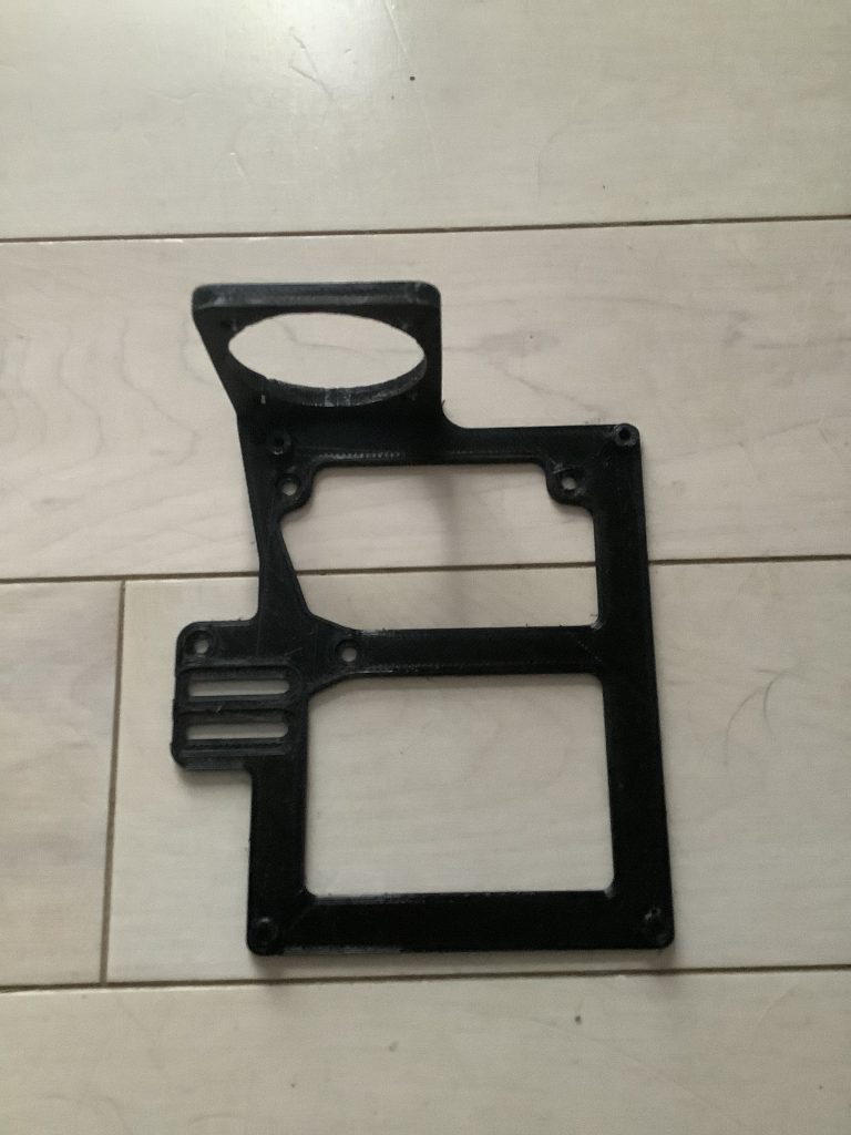
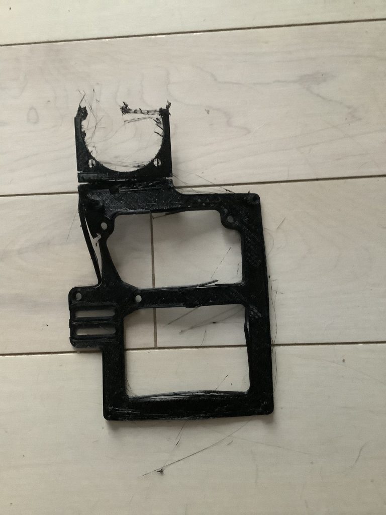
Then began my struggle (see the image below)


After meticulously dialing in my system, running retraction tests, heat towers, extrusion stepper modifications, extrusion multipliers, drying out filament and many many other steps to prep my system for a successful run with PETG prints…. My hotend kept jamming or under extruding, the extruder would click and click, and my prints were terrible.

After it would finish printing, it would break apart by simply touching it….

The solution to this…..

Open Simplify3D

Modify the FFF process

Go to the cooling tab

Set cooling on Layer 1 to 0

Remove all other setpoints

Uncheck the box that says Increase fan speed for layers below

Save, reslice and reprint

The result…

A solid print in PETG

PETG loves heat….and is ruined with cooling

Now It’s time for me to go back around and reconfigure my system with the extrusion multiplier, speed tests, heat towers, retraction tests….everything

ENDER 3 PRO – SIMPLIFY3D – CONFIGURING THE EXTRUSION MULTIPLIER

To figure this out, you can download Teaching Tech’s files on Thingiverse
https://www.thingiverse.com/thing:3071464

Unpack the files

Open up Simplify3d

Import the file called cube

Go to your processes and change the following settings:
On the Extruder tab
Set extrusion width to 0.48
Set extrusion multiplier to 1.00
Drag the Infill slider to Zero
On the Layer tab
Set Top Solid Layers to 0
Set Bottom Solid Layers to 0
Set Outline/Perimeter Shells to 1

Click Prepare to Print for the cube

You should see that the cube is 1 layer wide

Measure the wall thickness of this cube after it prints. My wall thickness measured in at 0.58

Now, to find out if the extrusion multiplier is accurate, run the following formula:
Desired Wall Thickness / Measured Wall Thickness * Extrusion multiplier = New Extrusion Multiplier
(Ex. 0.48 / 0.58 * 1.00 = 0.8275)


I will round the 0.8275 up to 0.83 and set this as my Extrusion Multiplier setting

Now to reprint the cube to ensure accuracy

PETG – TEMP TOWER – Simplify3D

In working with PETG, one of the first things you MUST do is print a temp tower, or heat tower, or temperature tower, or whatever you personally call it. This is essential, for understanding what temperatures work best with your filament, manufacturer, and color.

To print this temp tower, first, I had downloaded this model from thingiverse:
https://www.thingiverse.com/thing:3535163

Next you will want to unpack and import the model into Simplify3D

Then you will open up your Process settings

Navigate to the Temperature tab

Click on Primary Extruder

and Modify Layer 1

Layer 1 should be set to 260C

Now you will click Add Setpoint and continue to add setpoints until you have the following displayed in the Pre-Layer Temperature Setpoints box

Layer 1 – 260
Layer 41 – 255
Layer 81 – 250
Layer 121 – 245
Layer 161 – 240
Layer 201 – 235
Layer 241 – 230
Layer 281 – 225
Layer 321 – 220


Save the settings, Slice the tower, and print it

You will want to note which temperature produces the most efficient results without stringing, sagging, or any other issues.

And that will be the temperature in-which you print the rest of your objects with.

If you change Manufacturer, Color, Density, etc, you will want to reprint the tower to note the new settings.